Multislice 2D
2-beam dynamical diffraction
Setup
The structure is simple primitive square lattice with unique atom . The crystal is oriented along the [10 1] direction as shown in fig1-a which requires simulating a 10x10 super cell. For this case, the accelerated voltage has been voluntary chosen to allow for more Ewald sphere curvature. The configuration of the Ewald sphere is shown in fig1-b where the blue dots correspond to the reciprocal lattice rotated by from the zone axis [1 0] and the black dots correspond to the reciprocal lattice of the super cell setup. The beam intensities for and as a function of crystal thickness is shown in fig1-c.
| Potential | Ewald configuration | Diffraction pattern | Beams intensities |
|---|---|---|---|
 |
 |
 |
 |
Extinction distance
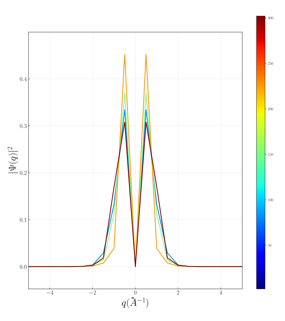
Below, the same simulation is run for different potential strengths.
Beam is not at the exact Bragg condition and its intensity with crystal thickness is mostly due to Ewald sphere curvature. Indeed, the oscillation period is independent of the potential strength and mostly depends on excitation error.
On the other hand, the beam being close to the Bragg condition, its extinction distance is sensitive to the strength of the potential. For this strongly excited beam, dynamical diffraction is present at all potential strengths but the kinematic regime is extended to larger crystal thickness at weaker potential.
 |
 |
 |
Rocking curve
Rocking curves are simulated by running simulations with various beam tilt angles ranging from 0 to 0.08 degrees.
The actual exact Bragg condition is satisfied for the . At this tilt angle, the Pendullosung thickness can be measured on the giving . The analytical approach would give .
The rocking curves around are characteristic of 2-beam theory and shown for .
| Rocking curves | at |
|---|---|
 |
 |
Padding
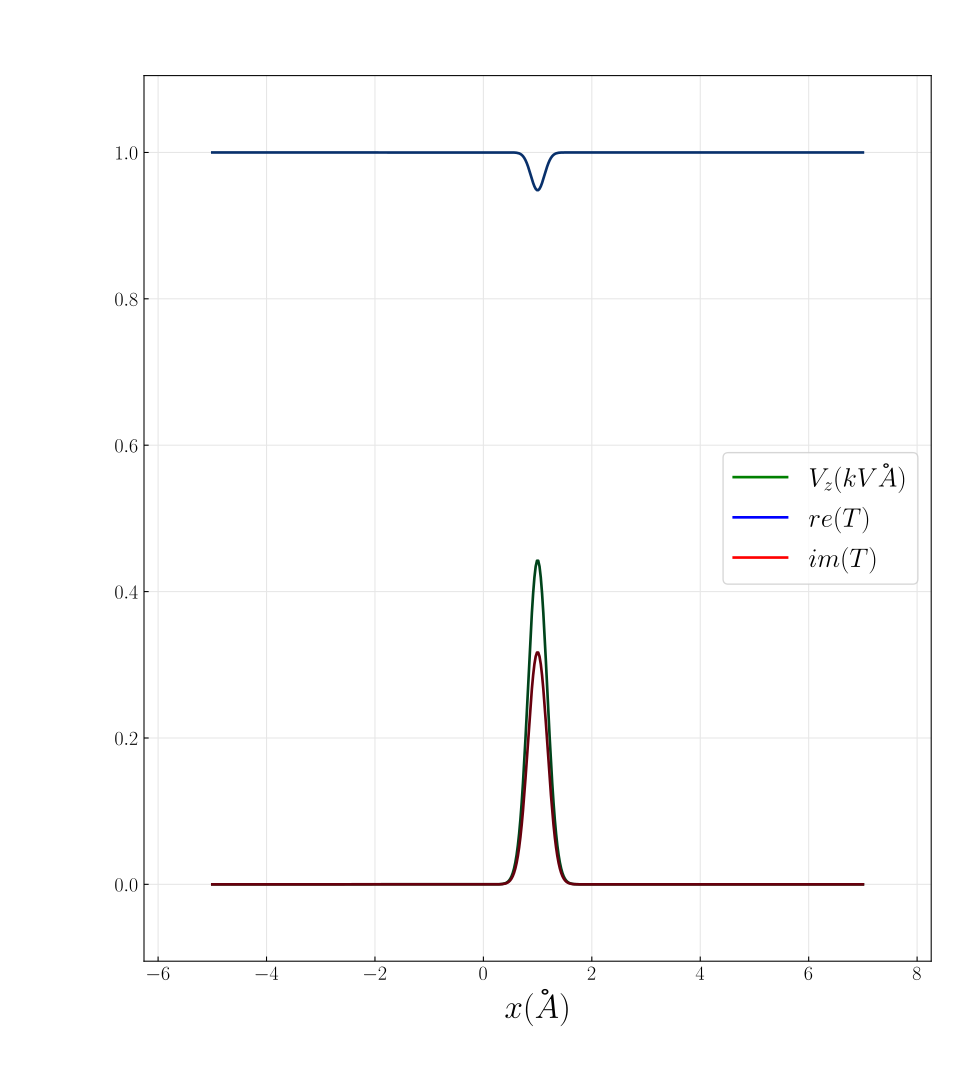
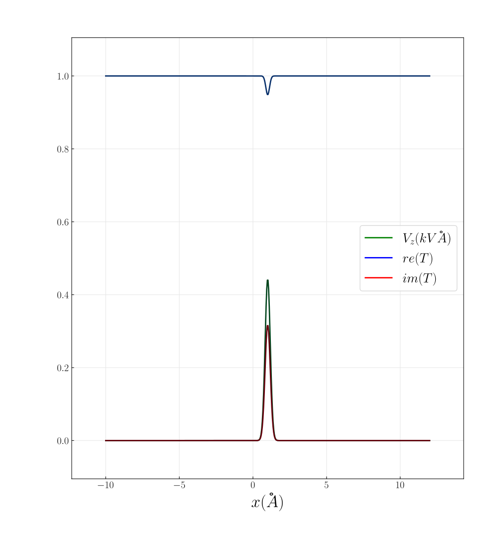
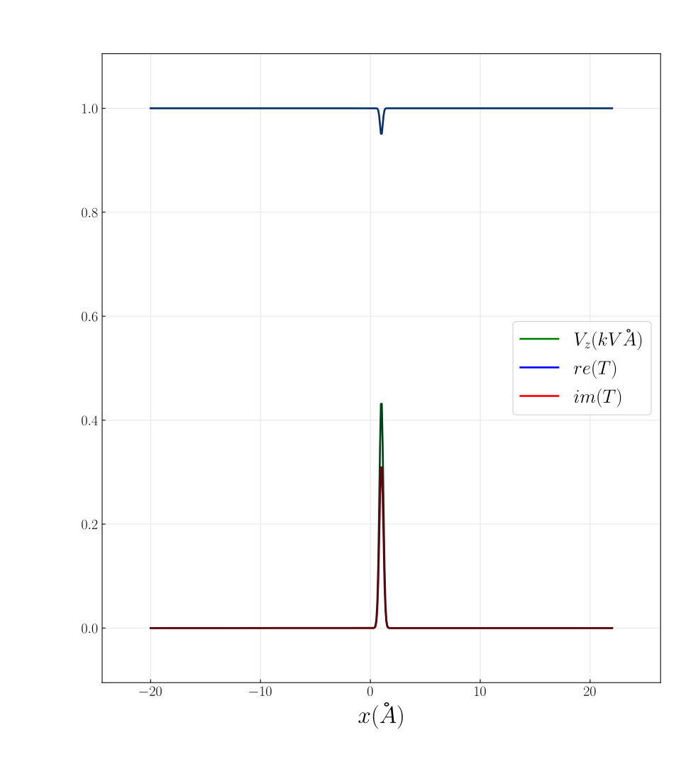
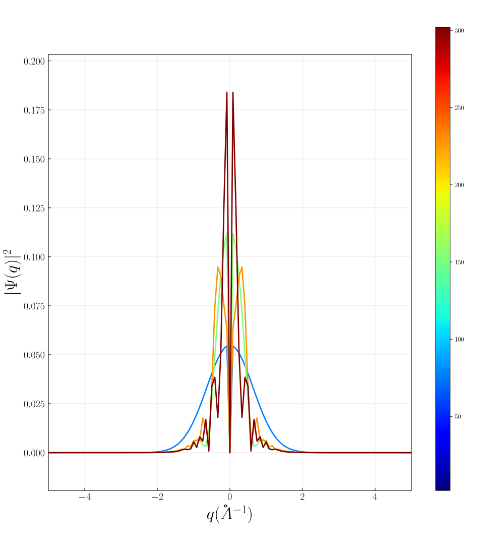
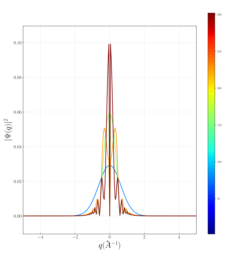
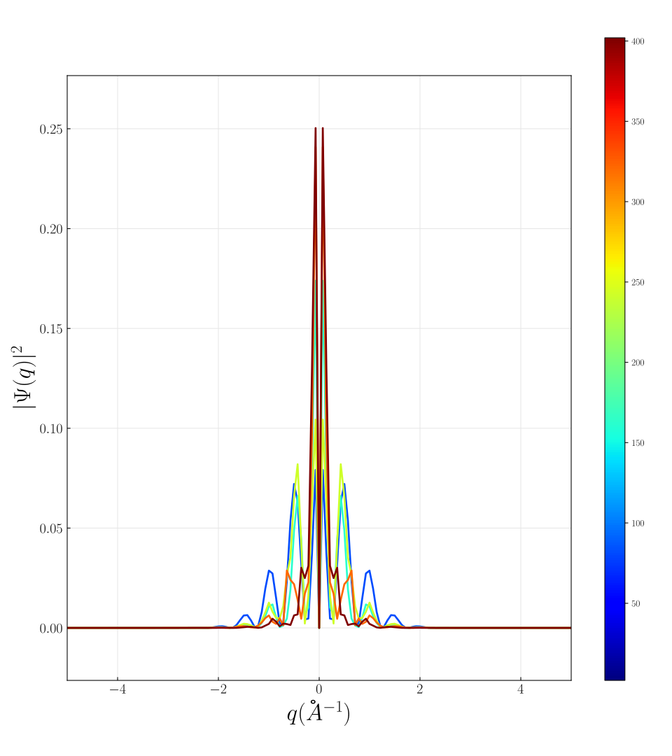
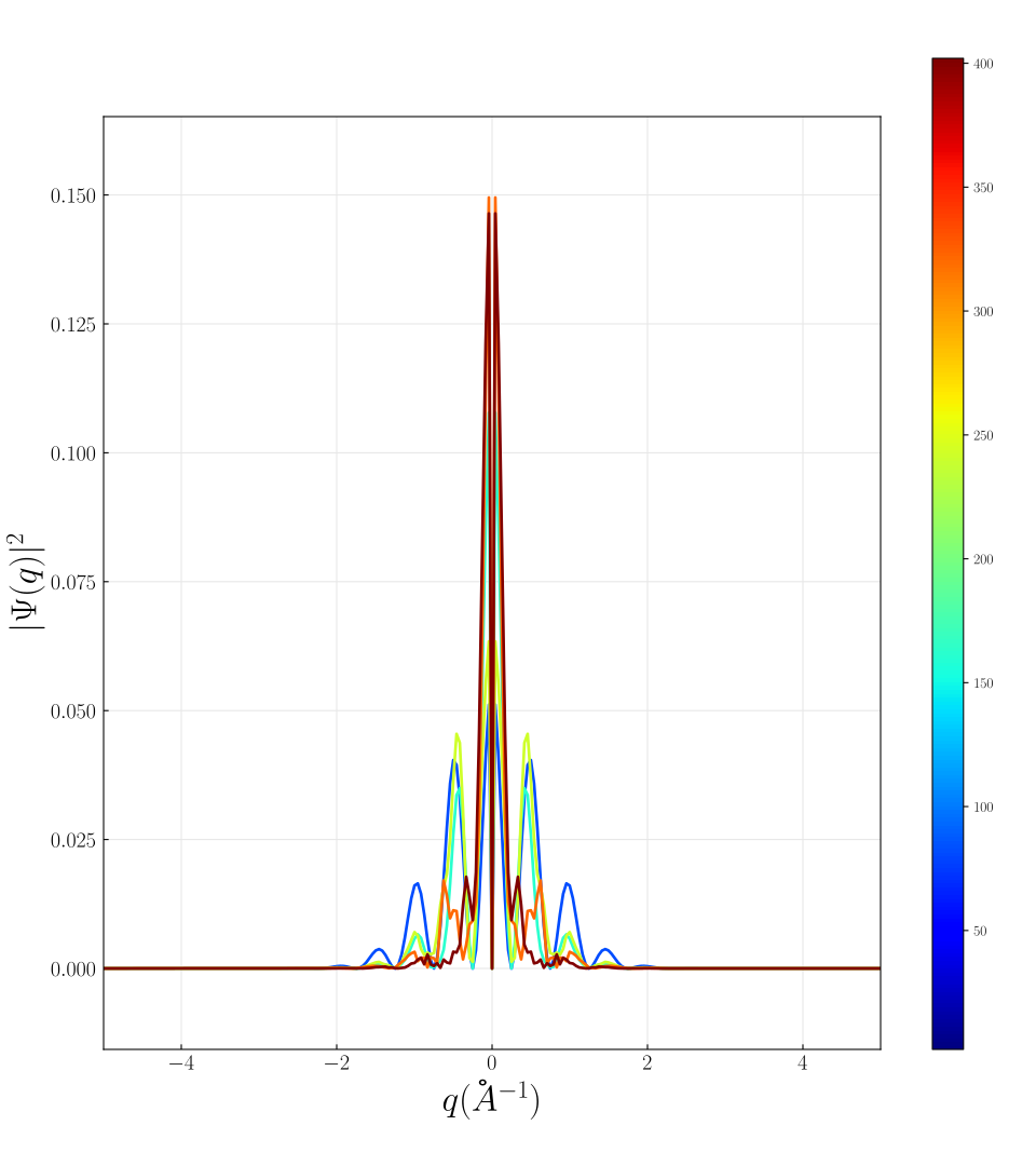
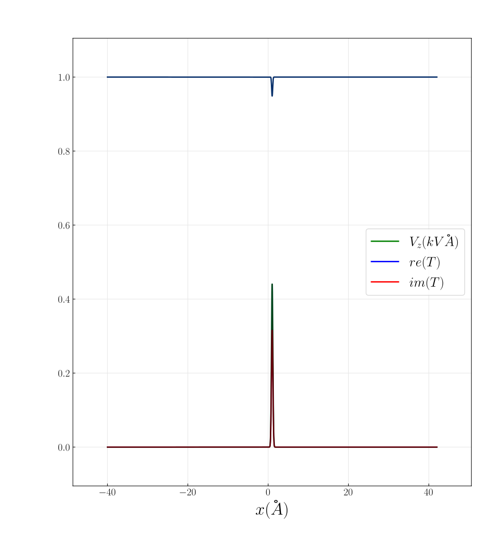
The purpose of this paragraph is to evaluate the effect of padding with zeros the potential of the sample in order to model finite size effects. The padding is expressed number of unit cells on each side of the sample.
Increasing padding for one periodic unit cell
| 0 | 5 | 10 | 30 | |
|---|---|---|---|---|
 |
 |
 |
 |
|
 |
 |
 |
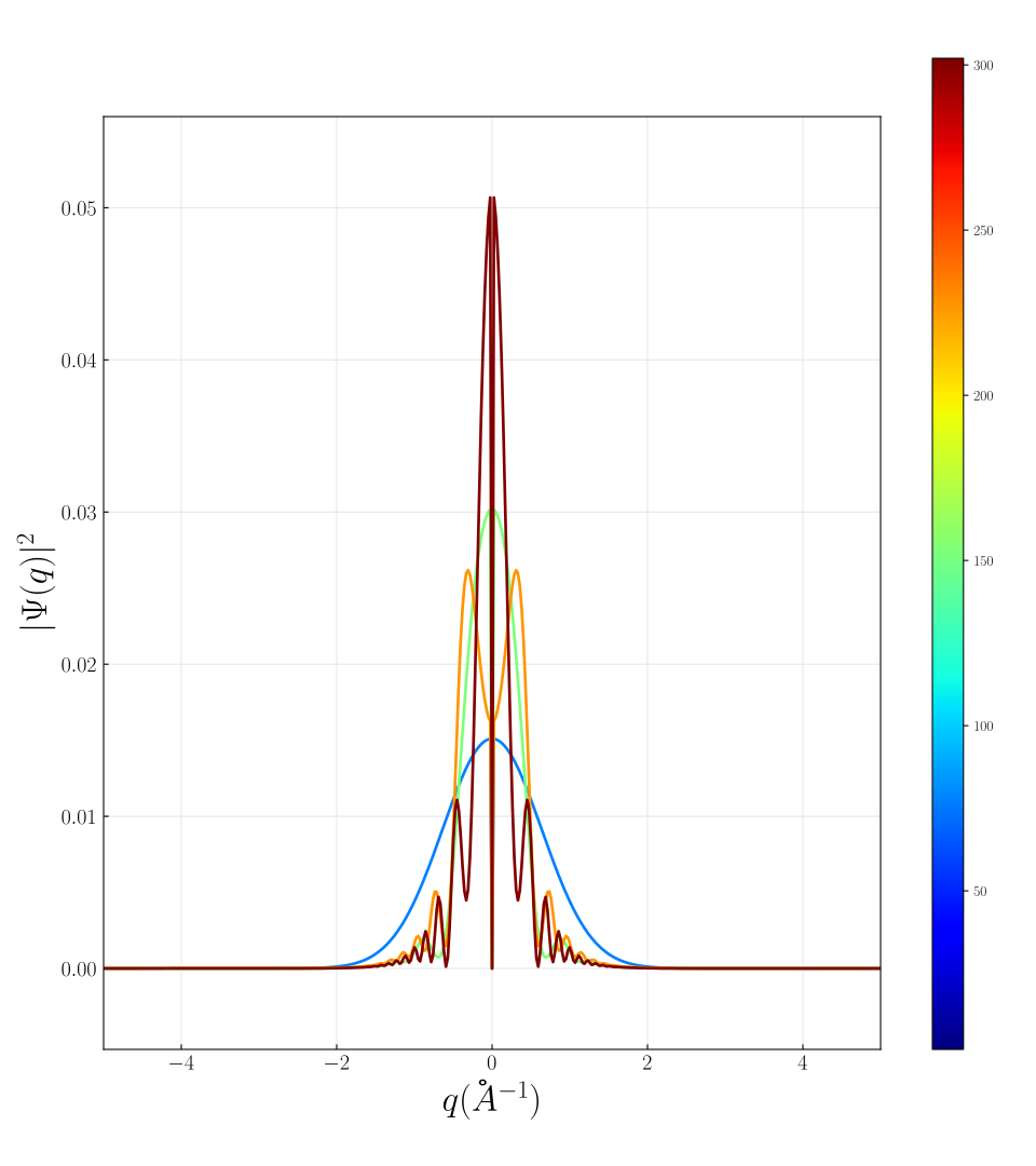 |
In this set of figures there is only one unit cell. In this case, the amount of padding has the same effect as increasing the size of the unit cell.
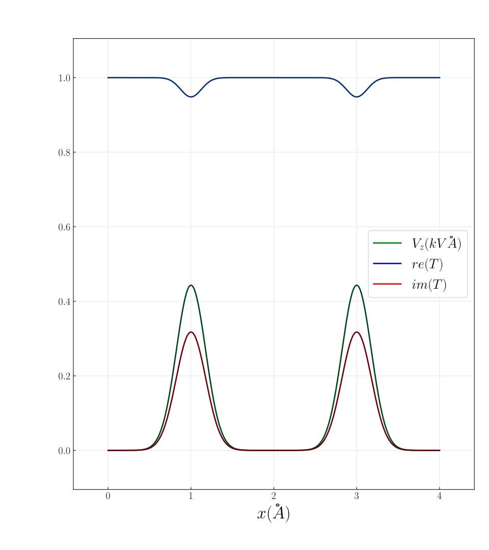
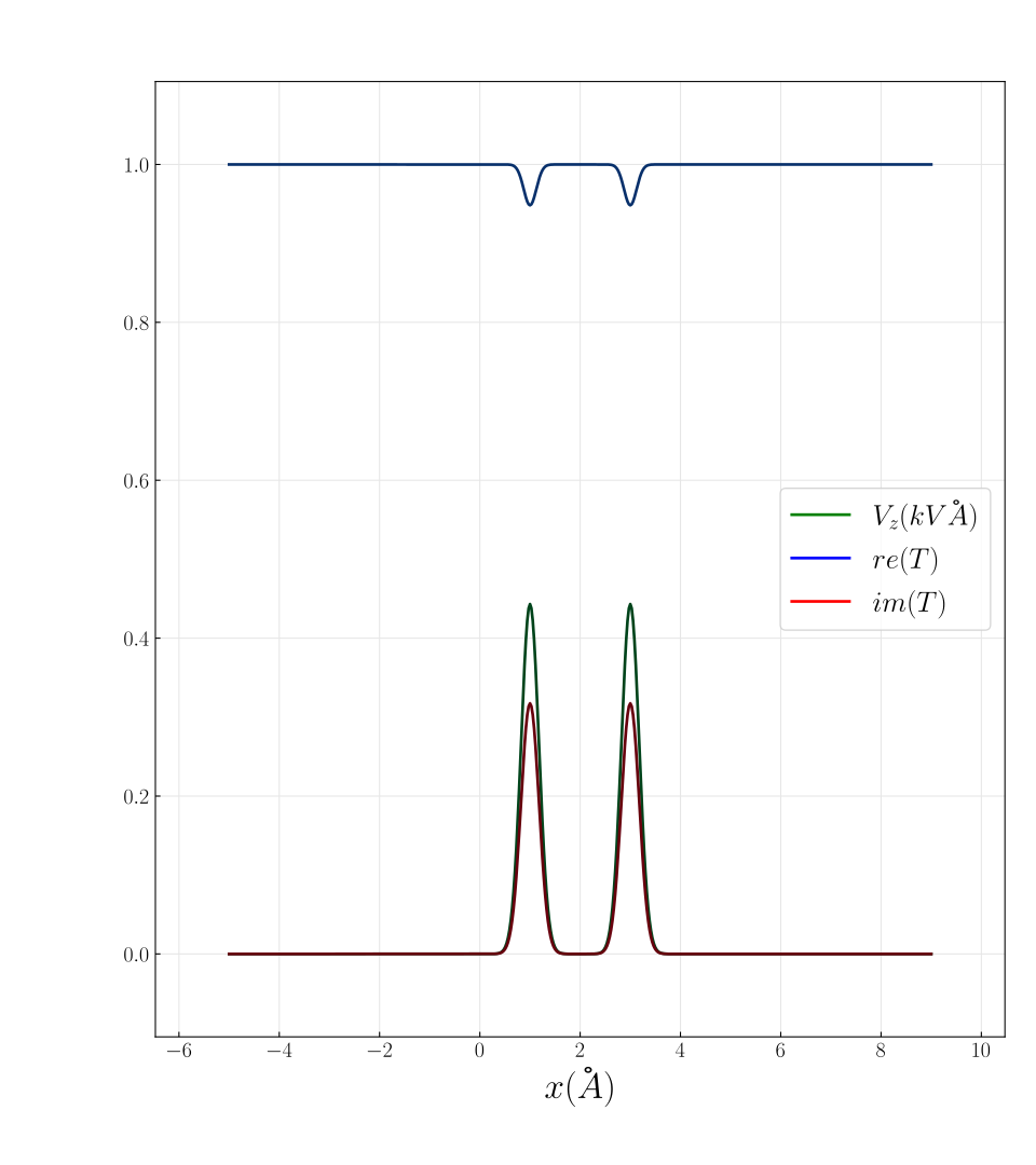
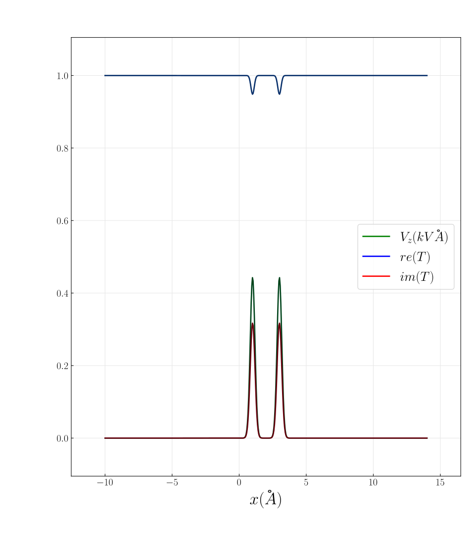
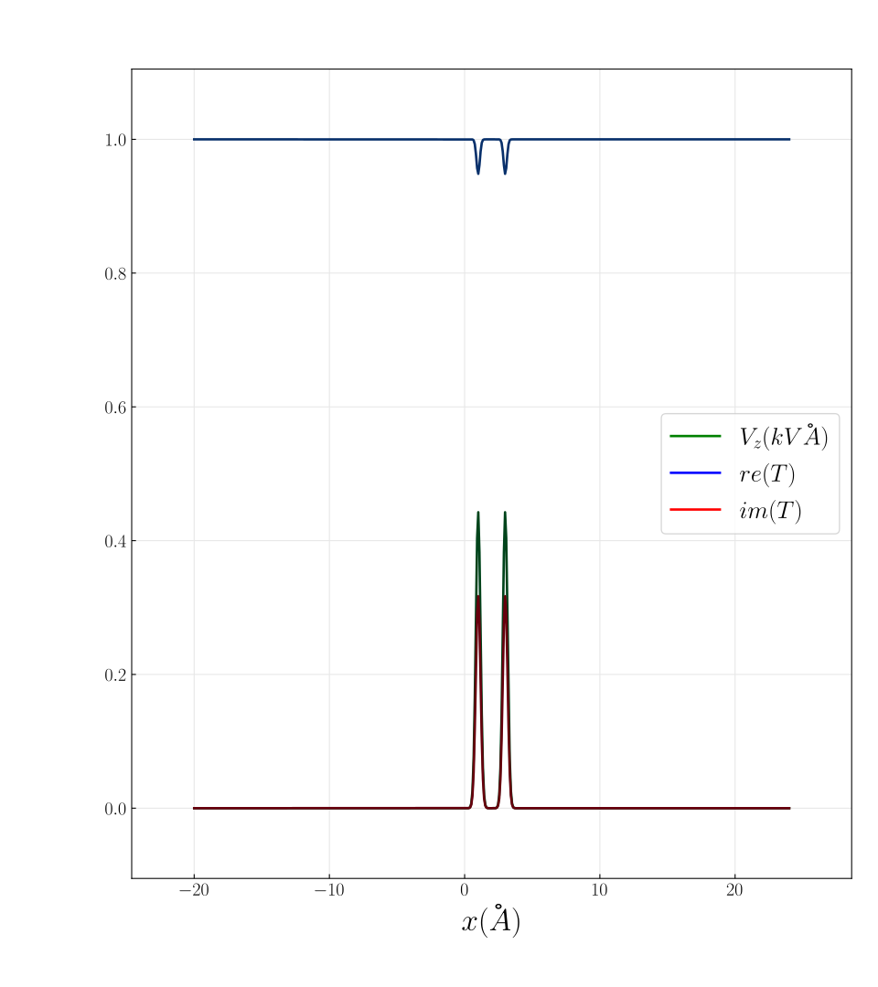
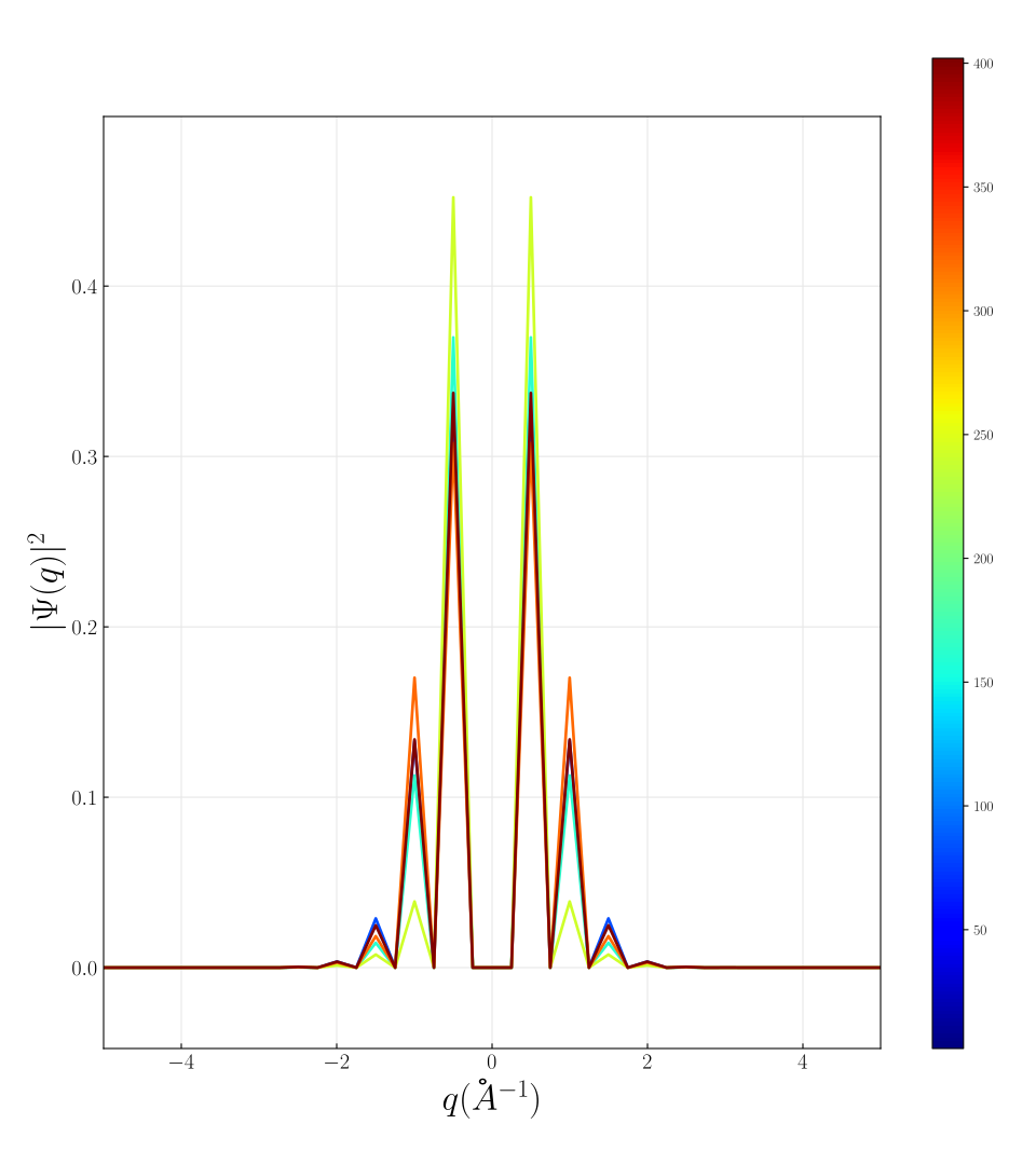
Increasing padding for two periodic unit cells
| 0 | 5 | 10 | 30 | |
|---|---|---|---|---|
 |
 |
 |
 |
|
 |
 |
 |
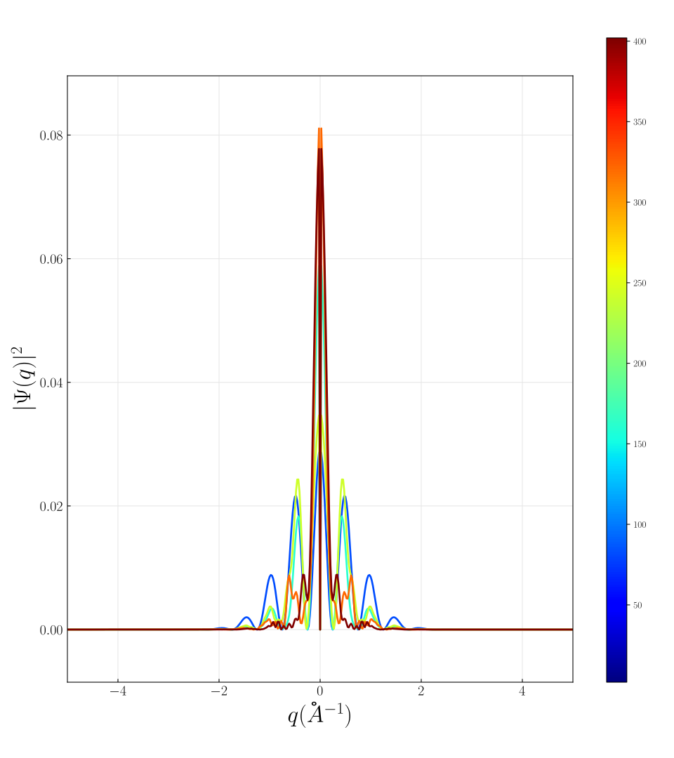 |
In this set, 2 periodic unit cells are used.
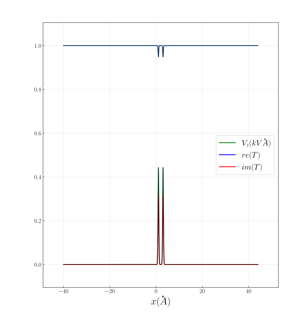
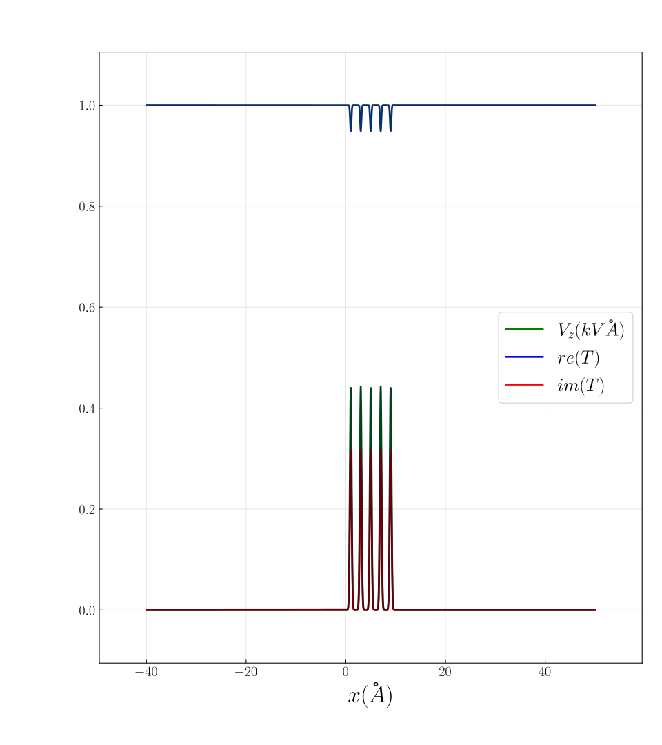
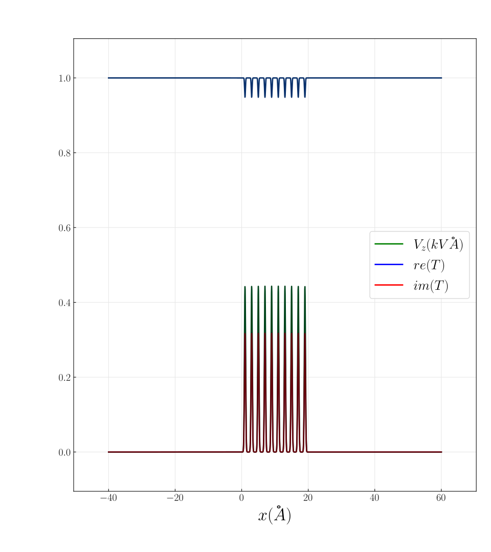
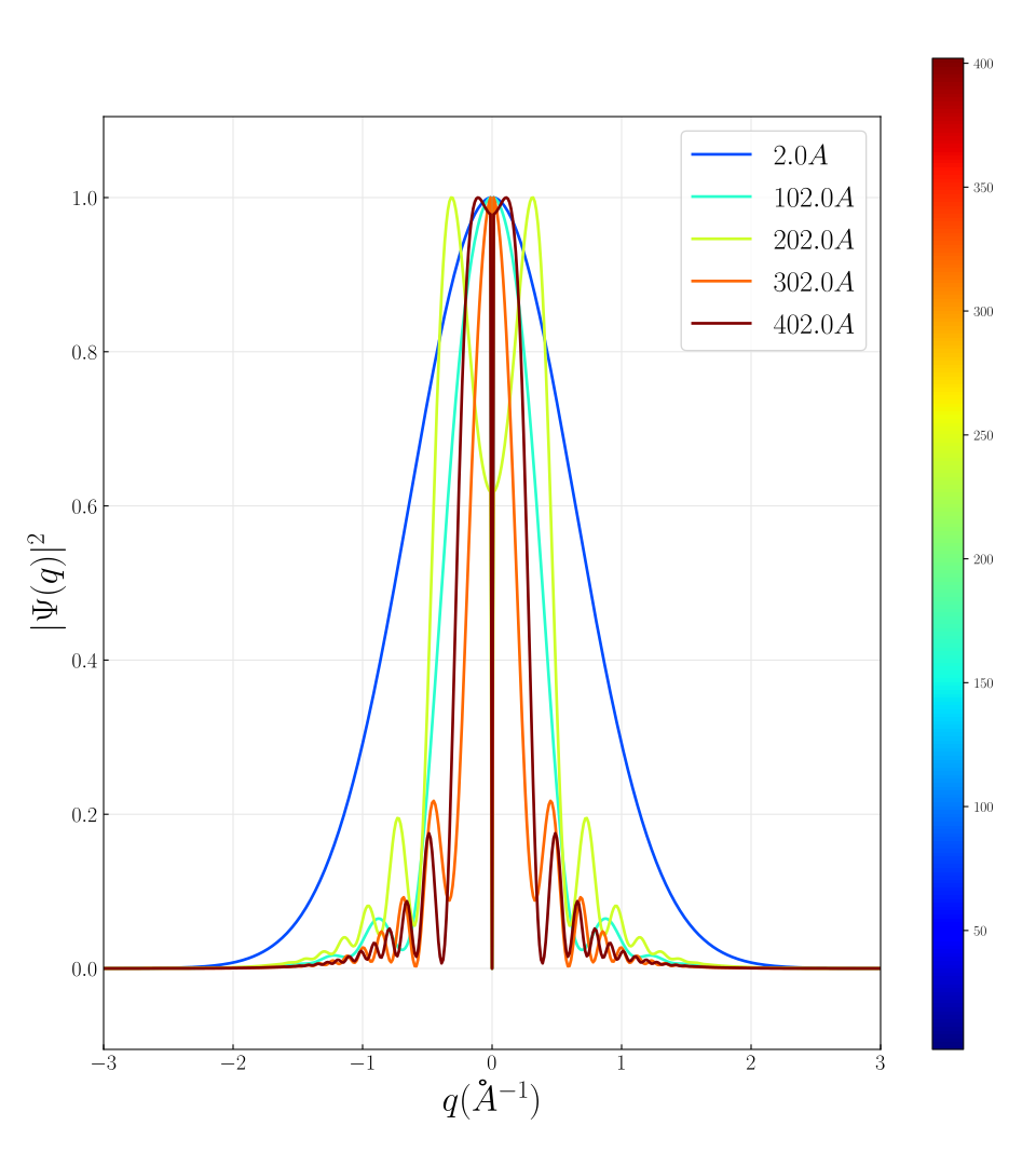
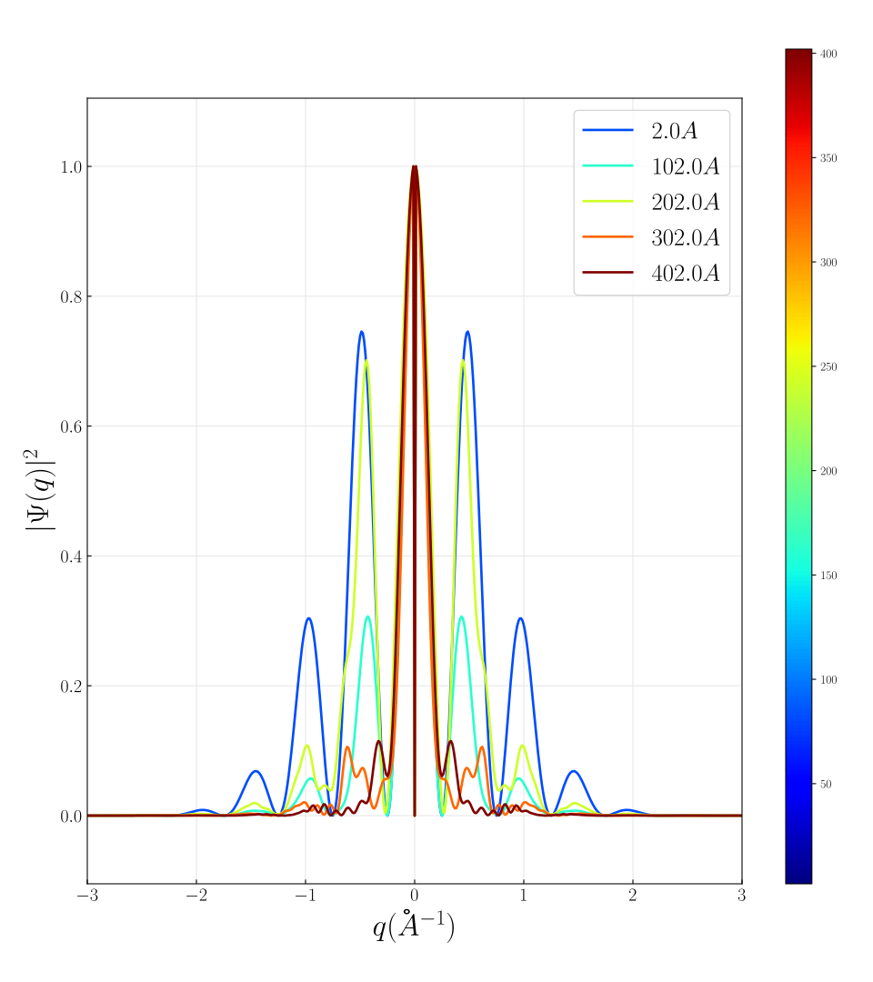
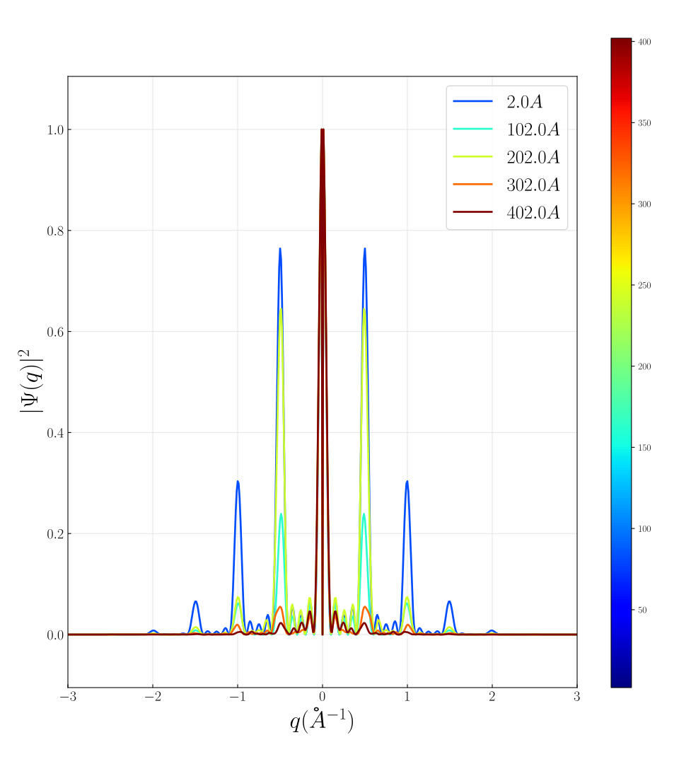
Large padding with increasing number of unit cells
| 1 | 2 | 5 | 10 | |
|---|---|---|---|---|
 |
 |
 |
 |
|
 |
 |
 |
 |
In this set, a padding of 20 unit cells is applied while the number of periodic unit cells is increased.
Real space convolution
Performing the convolution by direct integration, using the small angle approximation :
where with small angle and the Fresnel propagator , with and .
| Transmission | Propagator | |
|---|---|---|
 |
 |
 |
Below the real space transmission function, propagator and convolution product using the above integral and the FFT based multislice approach.