Multislice Simulation
Overview
A method used to determine the exit wave function(exit image) of an incident electron beam by solving Schrodinger's equation. The diffraction pattern is obtained as the Fourier transform of the exit image.
Links
- Wikipedia : A general overview.
- Cowley&Moodie, 1957 : original paper with in-depth analysis of the method.
- Kirkland, 2010 : Advanced computing in electron microscopy, 2010 is the main book reference for the implementation of the method available in the TEMSIM package.
- TEMSIM walk through of the source code.
- opensource softwares : Other available opensource implementations of multislice.
Assumptions and features
- Scattering is accounted for through the interacting electronic potential so that the electrons in the incident beam accelerated at potential have energies .
- Dynamical diffraction is naturally account for with this approach.
- Inelastic scattering is accounted for through the imaginary part of the potential which is also denoted as inelastic density function .
- The sample is divided in a series of slices orthogonal to the electrons propagation direction.
- Schrodinger's equation is solved by propagating the output wave function from one slice to the other using the parabolic approximation(Fresnel diffraction).
- The potential plays a similar role in Schrodinger's equation as the atomic susceptibility of a medium in response to an incident electromagnetic wave in Maxwell's equation.
- Since typically with the crystal volume, it is impractical to attempt solving the wave equation with a standard beam propagation method(BPM) and even less with a eigen value solver.
Method
The multislice approach solves the fast electron Schrodinger's equation in real space by direct integration along (incident beam direction) : where and is the interaction parameter. Note that by neglecting the second order derivative of the envelope function, this equation assumes that the potential is small compared to the incident beam energy.
Due to the exponentiation operator this must be approximated as :
where is the transmission function, is the propagator operator with the Fresnel propagator function and its Fourier transform .
Interaction parameter
The interaction parameter is expressed in , where is the incident wavelength, and is the relativistic mass with the Lorentz factor and the accelerating voltage energy.
It depends on the electron wavelength only and tends to the non relativistic case for small energy. This approximation is not valid at energies above .

Kinematic limit
If the specimen thickness is small the exponential transmission function can be approximated as . Far from the slice, the convolution with the propagator reduces to where is the transverse Fourier transform. Using the whole sample for the slice thickness and gives the diffraction pattern as :
where from the Fourier Projection Theorem. therefore corresponding to the kinematic scattering limit case. The notion of projected potential being also mentioned in zou, 2011.
The kinematic limit for which the slices are not interacting with one another also corresponds to the phase grating approximation approximation.
Fresnel propagator vs Fraunhofer diffraction
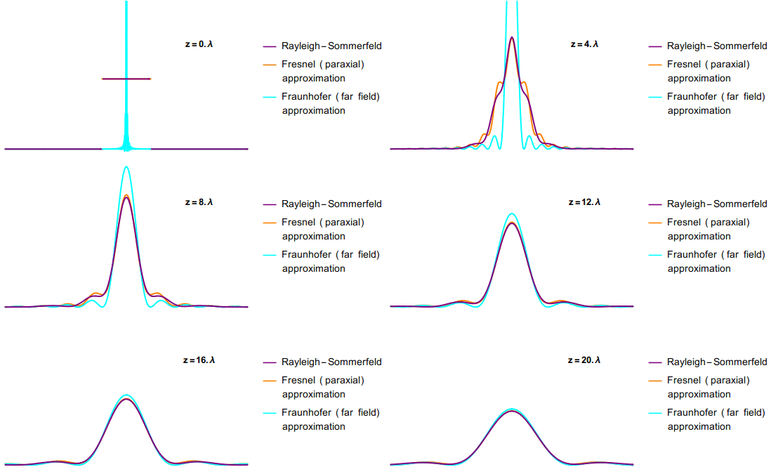
Below, a great visual comparison between Fresnel(used in multislice) and Fraunhofer(used in kinematic approximation) diffractions from Jacopo Bertolotti and a comparison with values that are relevant for electron diffraction.
| Fresnel vs Fraunhofer | relevant values for ED |
|---|---|
 |
 |
Element of theory from Cowley & Moodie
See paper summary of Cowley&Moodie,1957.
Practical aspects
Slicing

- The atoms should be aligned at the beginning of the slices so that the potential has effect only over a small fraction of the slice allowing cascading of the propagator therefore reducing error on the order of
- Too large slice thickness can produce artefacts
- Slice can not be arbitrarily small as they need to cover the full range of the atomic potential which might not be small enough for large atomic numbers of low voltages.
Bandwidth
- The potential must have rotational bandwidth-limited symmetry in reciprocal space.

- Individual components of the multislice approach are nearly exact when taken individually. The main source of errors comes from the combination of propagating (Fresnel approximation) and transmitting (phase grating approximation).
- The Fourier transform of bandwidth limited product of with is a convolution in reciprocal space . This is equivalent to successively sliding the Fourier transform of the transmission function along the fourier transform of the wave function . This causes aliasing if the full bandwidth is used (left fig). The remedy is to set (right fig). As a result only about 1/3 of the Fourier coefficients are used in practice.

Sampling
Correct sampling must be used to ensure reasonable conservation of the intensity :

TEMSIM source code
Application examples
GaAs
Slicing
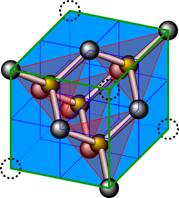
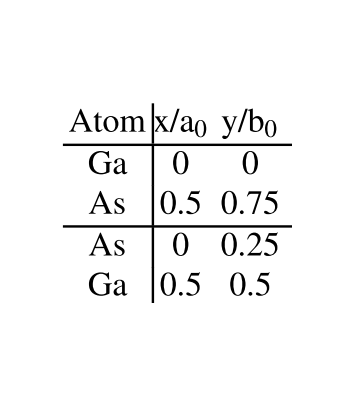
Cubic Face-centred zincblende structure with lattice constant with slice unit cell where , and slices are thick each.
| Structure | Slices [110] | Coords |
|---|---|---|
 |
 |
 |
Sampling
- The number of Fourier components (where ) controls the accuracy of the simulation. While components seems enough for thickness, it must be increased to for thickness.
- The real space domain is represented by a supercell composed of unit cells such that , . The supercell size is increased to increase reciprocal space sampling . The angular spacing at and .
- Increasing the resolution comes at the cost of a reduced bandwidth
Dynamical scattering
- Dynamical scattering appears as oscillating intensities as a function of thickness.
- atoms scatter more strongly which results in fainter signal at the exit image than atoms.
| at | effect of microscope | |
|---|---|---|
 |
 |
 |
Silicon nitride
hexagonal structure with lattice constant with 14 atoms per unit cell () with rectangular super unit cell where and each with thickness .
| Structure N(white), Si(black) | Slices [001] | Exit image magnitude |
|---|---|---|
 |
 |
 |